shop

REBUILD


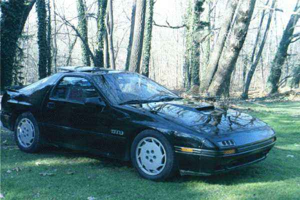
A pictoral review of a 13B rebuild including: porting, oil system modifications, engine removal and reinstallation


shop
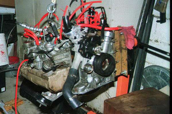
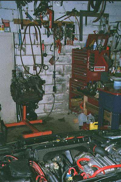
The "rebuild shop" was nothing more than an unheated concrete garage with a full complement of tools including overhead chain hoist, 20 gal. parts washer and air.

Notes:

  • Disconnect the battery (unless you've always wanted curley hair)
  • Always chock a wheel or two
  • Remove the hood
  • Keep a fire extinguisher handy (yep, parts cleaner IS flamable)
  • Put a pad over both fenders and the nose (you're going to be spending a lot of time with your rodeo buckle riding the paint job otherwise)
  • You can hang the starter from its wires if you are CAREFUL (there is a hidden engine / transmission bolt hidden behind the starter BTW).
  • Wire the P/S and A/C to the fender to keep the hoses from being pinched - you don't have to disconnect them.

old coming out
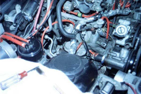
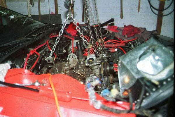
Removing the engine with the overhead chain hoist looked like a good idea - and it DID work okay - but it is a BAD idea for putting the engine BACK IN. The next engine swap will be done with a cherry picker so that lateral and fore / aft adjustments can be made more easily. Without a cherry picker it took about half an hour coming out and four hours going back in. With a cherry picker I estimate less than a quarter of that time would be needed.

Notes:

  • Support the transmission with the front of the housing slightly raised - a scissor jack works well
  • Remove the vacuum lines, throttle body, dynamic chamber, upper and lower intake manifolds before pulling the engine (carefully mark vacuum lines for reassembly (REALLY do it - the vacuum spider can get a little confusing).
  • CAREFULLY disconnect the engine wiring harness from the various connectors - marking them for reassembly - and place the harness safely out of the way along the passenger side fender (some people recommend pulling the entire harness through the firewall after disconnecting it from the ECU but I think that the 18 year old harness is too brittle for that twisting and flexing. The last thing you need is a short internal to the harness)
  • Carefully note the ground attached to the firewall at the vehicle ID plaque and beneath the dynamic chamber aft of the BAC. This ground, if not reattached or if loose can almost guarantee you will get the dreaded 3800 rpm hesitation.

13b disassembly 
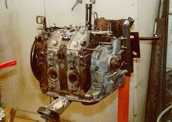
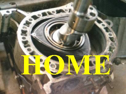
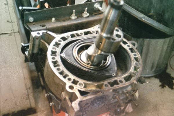
In order to rotate the engine while it is attached to an engine stand you will have to fabricate an adapter. A 15" x 12" piece of 3/16" steel plate with four 90 degree bends will do fine. Drill the adapter to bolt to the front housing (not front cover) A/C bracket holes. Taking the 13B apart is really very straight forward, sort of like unstacking a loaf a bread. In this pic the rear housing has been removed after taking out the tension bolts (IN ORDER), the rear rotor was then lifted up off of the eccentric shaft and then the rear rotor housing and intermediate housings were raised off the shaft as well - leaving what you see. It is useful to carefully note locations from which you take various seals and springs even if you are planning to replace everything small (which is recommended) - as it is an educational experience to relate worn areas of one part to offending opposing part.

Notes:

  • It is highly recommended to remove the flywheel nut with an impact wrench. There are other techniques but it is worth it to beg, borrow or steal a 300+ lb. air gun TRUST ME.
  • Release the tension bolts in the order specified in the manual or else you may warp the rotor housings
  • It is recommended that parts be put in prepared containers, baggies or racks so that they can ACTUALLY BE FOUND when you go to reassemble
  • Keep a fire extinguisher handy (yep, parts cleaner IS flamable)

rotor wash
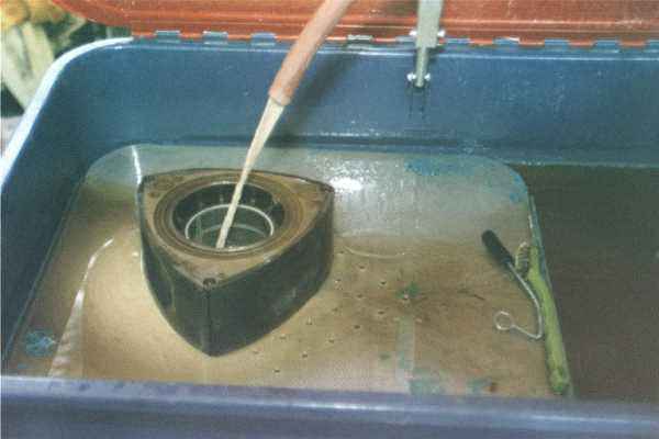
Perhaps the most important steps in rebuilding is cleaning and spec'ing parts. A parts washer is invaluble. Castrol Super Clean is excellent (caustic). Rotors and housings get multiple scrubs in the mineral bath with brass brushes. Take care to remove ALL old seal and gasket material from every part. Yes, this is tedious, frustrating and aggravating - yet necessary. For a good rebuild the washed parts should look almost new. Once completely clean one can get meaningful measurements to determine re-usability of subcomponents.

Notes:

  • Use brass brushes instead of steel to protect the many aluminum surfaces
  • Grind down a couple of small flat screw drivers to the EXACT size of the water seal grooves and take as much time as you need to get the channels perfectly clean with them.
  • One can use pieces of old apex seal and side seal to scrape out the corresponding seal grooves. Take care, the old seals are SHARP. Sometimes it may take several wash / soak cycles to get the old seals and springs out of their grooves PRIOR to actually cleaning the rotors or housings.
  • Gasket removal is like seal removal but WORSE. Only one solution - ELBOW GREASE. Many, many razor blades or flat scrapers will be used. Gasket solvent may help some but I think it is mostly wishful thinking.
  • If you don't get the parts completely clean you'll never know whether the housings are warped or have unacceptable stepped wear -and you don't want to assemble an engine that will just go south immediately - so clean 'em and spec 'em.

prepped rotorsProperly cleaned housings show no residue in the inner or outer water seal grooves and generally look nearly new.

Notes:

  • Check for chrome flaking around the perimeter of the rotor housings - matchhead sized flakes that you CAN'T CATCH TOUR FINGER NAIL IN are okay - larger are not.
  • Look for wear around the exhaust ports. Again, grooves that you can catch your nail in call for rejection of the housing
  • Carefully mic the housing for width and check the shop manual for tolerances (You will also mic the rotor for width and compare to the housing figures for variance as well as the eccentric shaft to bearing surfaces for variance etc., etc.)
  • Check the water passages for corrosion and failed passage walls. Clean the corrosion and reject the housing if there are broken walls
  • Lightly sand the perimeter of the iron with 400# wet / dry using a PERFECTLY FLAT sanding block

https://pbgarrott.tripod.com/ecc3bf3240_hp60.jpg 
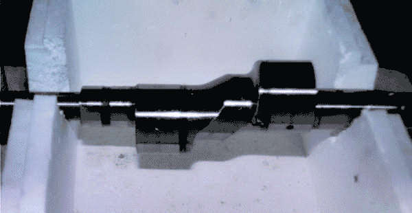
You will need to fabricate a stand for the eccentric shaft so that measurements and mods may be performed. A heavy polystyrene box works okay but take care to keep poly bits out of the oil holes

Notes:

  • Mic the bearing surfaces carefully - this is the high wear area. The shaft will probably meet specs but it is not unusual to have to replace front or rear main bearings (if copper color shows anywhere except the bearing weld line - replace it)

ecc. jets
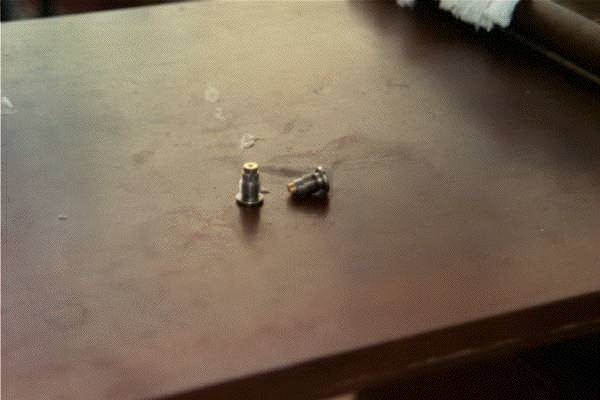
It is a fact that engine oil carries away about 40% of the 13B's generated heat so greater oil flow is probably not a bad thing. These are 2 mm. Weber jets that have been modified to replace the ball and spring eccentric shaft oil valves. They have been JB Welded to the original carrier and will be reinserted in place of the ball valve. This engine also received an 80 lb. rear oil pressure regulator and a shimmed front regulator. The oil flow was further enhanced by swapping the NA oil pump for a TII one.

mics 
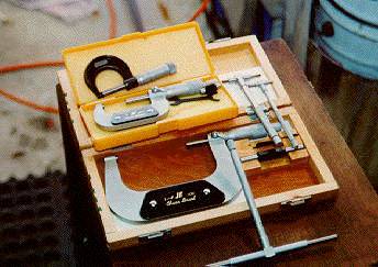
Since you'll probably put over a thousand dollars in parts into your rebuild it would be pretty silly to assemble without knowing whether the supporting assemblies will function to spec. Bite the bullet and buy or fabricate gauges to assure that your rebuild meets specs.

Notes:

  • These ID / OD mics and calipers came from Travers and cost less than $200. Well worth it as insurance.

dial gauge
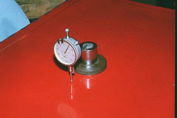
If you are a litte daffy (like me) you can make your own gauges. This dial gauge is made from a large socket filled with lead and attached to a magnet on the base side and an old dial gauge on the other end. After spend hours and maybe $15 I found I could buy one from Travers for $25 - base, gauge and mount.

https://pbgarrott.tripod.com/badhousingpj70.jpg 
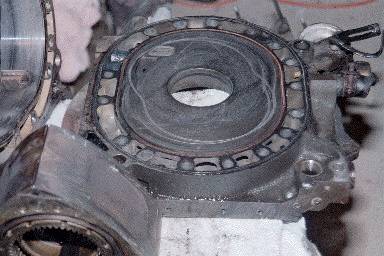
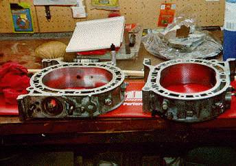
Trust me, not all assemblies that are destined to fail are as obviously trashed as this intermediate housing. A piece of apex seal was carried around and around digging a 1/8" deep groove in the face. It killed the housing but nicely shows the rotor's eccentric path.

baggies
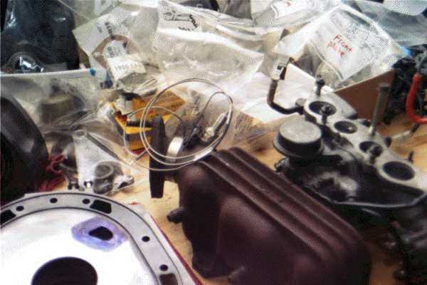
If you are in a humid climate it is useful to bag and lable your parts as they are cleaned. This keeps them from corroding and gives you a fighting chance at finding the part when you want to reassemble.

template
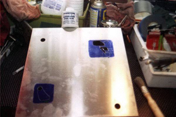
This engine was to be ported to Mazdatrix 6-port specs. The M'trix template arrived as just an aluminum sheet painted with dychem and etched with the outlines of the proposed port shapes.

Notes:

  • Only use carbide bits - anything else is a waste of time
  • An air powered die grinder works quickly but is prone to "walking" (and ruining your irons). A Dremel tool works adequately and tended to be more manageable for me.
  • A 80 - 120 grit emery flapper wheel does a nice job of finishing rough ports to a mirror shine. Some say that a bit of texture left at the port exit will keep the fuel mixture from adhering to the port wall so mirror finishes aren't always best downstream of the injectors.

template on dowel
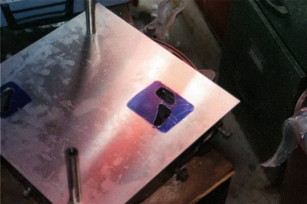
The template that you cut out (to the scribed shape) is placed over the dowels on the iron (which has had dychem painted around the existing port) and serves as a guide for etching the new port shape onto the housing.

Notes:

  • Grind slowly. If the bit walks across the face of the housing it can ruin it $$$
  • The housing is toast if you hole the water jacket - take care to blend the new port shape into the existing tunnel.

etched iron
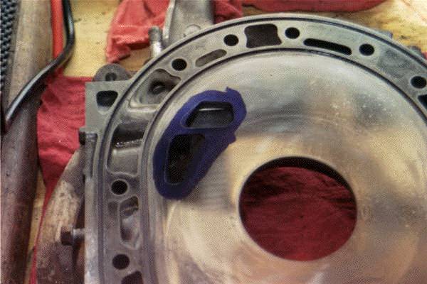
This is an etched iron prior to any grinding.

new on stand shortIt takes about two and a half hours to reassemble the engine once all the parts meet spec for re-use or new ones have been acquired. It goes back together the opposite of how it came apart (sorry, bad joke).

Notes:

  • This is where a rotating engine stand with adapter pays for itself. You have to rotate the block several times as the engine is assembled.
  • Take care to place the water seals so they won't slide out of their grooves and get pinched in assembly - liberal use of hylomar to hold o-rings and such in place is a good idea.
  • Carefully sand / emery the rotor side seals to the spec'ed tolerances. The new parts are oversize and will bind if one tries to install without sizing.
  • Use 3rd gen. corner seal springs which are a much better design than earlier ones.
  • Take your time in positioning oil seals and their corresponding springs - there is only one way that they go in and it is NOT obvious. Read the shop manual and double check.
  • Be VERY careful in assembling the front eccentric shaft run out / end play . It is quite easy to let the spacer ring bite a bearing. It's particularly important to take your time here as it is possible that you will have to take the front cover off several times and swap spacers to get the right run out. Each time you remove the front nut and retighten you have the opportunity to bite a bearing if it slips off center.
  • Before assembling the intake, sand or wire brush the grounds and take an emery board and clean up the contacts on the various senders and connectors - this can save sobbing and hair-pulling later.
  • An aluminum block-off plate was installed over the oil pump opening after the pump drive shaft and gear were removed from the front cover.
  • Injectors were replaced with equivilent metric bolts and washers
  • Just for effect, the iron housings were painted the color of the car but the aluminum pieces were left natural.

wire relo
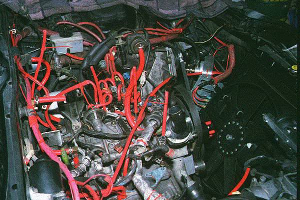
This engine is receiving a supercharger which needs a lot of elbow room so the engine wire harness needed to be routed out of the way under the secondary fuel rail. The cold-start injector was removed and JB Welded over. The fuel pressure regulator was removed as well (replaced with an adjustable one downstream - see "Fuel")

new on standNote the absence of the oil injector lines and pump. This engine will run premix exclusively. The old injectors were found to be inconsistant in their oil injection rates (if they injected at all).

Notes:

  • All vacuum lines were replaced with thick wall Akimoto silicone which is less prone to kinking than thinner walled hose. In those cases where there is a 90 degree bend, a loop of hose (270 degrees like an interstate cloverleaf) was used to further reduce chance of kinking.
  • The passenger side engine mount is attached loosely attached to the engine and the driver side mount is loose in the chassis as the engine is readied for installation
  • As the engine is nudged micron by micron into mating with the transmission it is sometimes useful to rotate the eccentric shaft slightly with a wrench to help the splines align. Be sure the trans is in gear.
  • Don't force the engine and transmission together. They should mate smoothly and easily when aligned correctly. NEVER try to force them together by progressively tightening the bolts.

new no intake
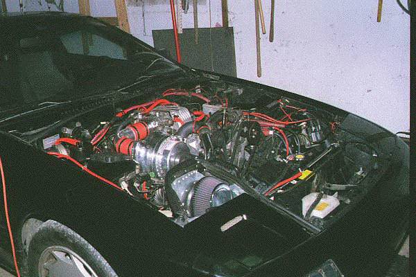
Once mated to the transmission it is only a matter of reattaching the wiring harness and intake.

Notes:

  • Make sure you have a GOOD ground below the dynamic chamber
  • Go slow, be thorough. Make sure you have excellent seals at all the intake joints. An air leak under the dynamic chamber is enough to drive you loony.

newActual start to finish of this rebuild was two months owing to slow delivery of some parts. This is plenty of time for parts that you removed earlier to get tarnished / corroded (another plug for baggies).

Notes:

  • This engine required a "flood start" routine to fire up - which isn't unusual
  • This engine went together with a blend of '87 and '88 parts and the end result wasn't always good. The '87 CAS didn't like living in the '88 engine. A swap to an '88 CAS solved it (figuring it out wasn't fun though).
  • Break-in consisted of 40 minutes at fast idle and then an oil / filter change. Then 500 miles of no boost and a 3500 rpm. ceiling followed by another oil / filter change. After that was 500 miles of mild boost and a 4500 rpm limit . . . oil changed again. Finally a last 500 miles with unrestricted boost and a last oil change before going back to the usual 2500 mile interval.